Introduction
Typically, drawing units in AutoCAD are millimeters. Therefore, to calculate the area values in square meters, it is necessary to resort to the procedure of mathematical transformations. There is no convenient universal tool in AutoCAD for calculating areas in square meters or any other units. However, there are a number of applications that allow you to solve this problem quite easily.
The most convenient way to calculate any area in square meters in AutoCAD is using the AreaTester application.
Before you start using it, you need to make a small setup of the app.
Step 1. Entering the application settings
Launch the application in AutoCAD using the ATST command
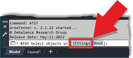
The settings of the AreaTester application are accessed through the SEttings option on the command line
Immediately after entering the command, select the SEttings option and get to the Program Settings dialog box (see Fig. 2):
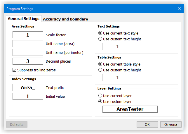
Program Settings Dialog Box.
Step 2. Setting the units for area and perimeter
In the Program Settings dialog box, in the General Settings tab, set the scale factor value to 1000 (see Fig. 3):
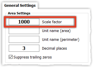
To measure areas in square meters, you need to set the scale factor to 1000
With this scale factor value, the application will automatically recalculate and display all areas in square meters, and perimeter values in meters.
After setting the scale factor, you can set the textual values for area and perimeter unit suffixes. To do this, in the Unit name (area) edit box, enter the value sq. m, and in the Unit name (perimeter), set the value m.
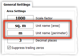
Assigning suffixes for area and perimeter units
Now close the Program Settings window by clicking the OK button. The set values of the setting parameters will be automatically saved.
Step 3. Launching the application and calculating the area
Now calculate the required areas. After the previously made settings, the values of all detected areas will be displayed in square meters.
To do this, launch the AreaTester application in AutoCAD using the ATST command. Next, select a fragment of the drawing or a group of objects among which the area will be measured (see Fig. 5):
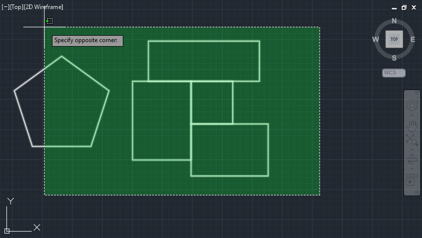
Select a group of objects for the subsequent calculation of areas
After that, you need to select the required areas with the cursor. The specified areas will be added to the list of areas and perimeters of the main application window.
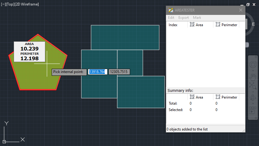
Add the necessary areas to the list of the main application window
The AreaTester application will automatically sum all selected areas and their perimeters. The total value of areas and perimeters will be displayed at the bottom of the main application window in the Total row in the Summary info list.
The area values, as mentioned above, will be displayed in square meters and the perimeter values in meters.
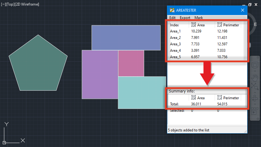
The AreaTester app automatically sums all areas and perimeters
Step 4. Inserting area values to the drawing
To insert area values in square meters to the drawing, use the corresponding option in the Mark menu item of the main application window.
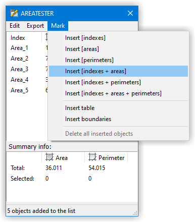
Tools from the Mark menu item of the main application window allow you to insert data from the generated list to the drawing
For example, when selecting the Insert [indexes + areas] option, index values and area values from the generated list will be inserted to the drawing.
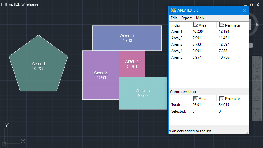
Inserting data to the drawing from the generated list of areas and perimeters
Step 5. Export of the generated data
If necessary, the generated data can be saved in an external file. For example, to save the measured area values in a text file, select the Export to *.TXT option in the Export menu item of the main application window.
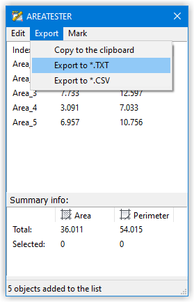
Export of data from the list to an external file is carried out from the menu item Export
After that, you need to select a folder and specify a file name.
