Entering AreaTester settings
Access to the settings of the AreaTester app is carried out through the SEttings option in the AutoCAD command line. The SEttings option becomes available immediately after launching the application (see Fig. 1):
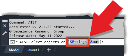
Fig. 1
The settings of the AreaTester application are accessed via the SEttings option on the AutoCAD command line
The settings of the AreaTester application are accessed via the SEttings option on the AutoCAD command line
The General Settings tab
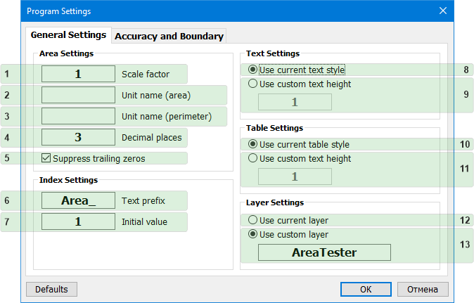
Fig. 2
The AreaTester program settings. General Settings tab
The AreaTester program settings. General Settings tab
Area Settings
- (1) Scale factor • The edit box for setting scale factor parameter. A values of areas and perimeters added to the list of the main window depend on the specified scale factor parameter. Examples of scale factor values corresponding to different units of area and perimeter are presented in the following Table 1:
| Scale factor | Units of areas | Units of perimeters |
|---|---|---|
| 1 | Square millimeter | Millimeter |
| 10 | Square centimeter | Centimeter |
| 25,4 | Square inch | Inch |
| 100 | Square decimeter | Decimeter |
| 304,8 | Square foot | Foot |
| 1000 | Square meter | Meter |
Table 1
Table of scale factor values for various units of area and perimeter
Table of scale factor values for various units of area and perimeter
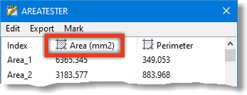
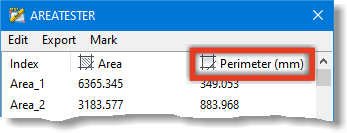
- (2) Unit name (area) • The edit box for setting the textual name of the area units added to the list of the main window. For example, the area units can be set to the following values: mm2, cm2, m2. Area units will be displayed in the header of the Area column in the list of the main window app.
- (3) Unit name (perimeter) • The edit box for setting the textual name of the perimeter units added to the list of the main window. For example, the perimeter units can be set to the following values: mm, cm, m. Perimeter units will be displayed in the header of the Perimeter column in the list of the main window app.
- (4) Decimal places • The edit box for setting number of decimal places in the values of areas and perimeters added to the list of the main window.
- (5) Suppress trailing zeros • Suppresses trailing zeros in the decimal values of areas and perimeters added to the list of the main window.
Index Settings
- (6) Text prefix • The edit box for setting text prefix before the index value in the Index column in the list of main window.
- (7) Initial value • From the specified value in this edit box, the indexes will be numbered and incremented when new areas are added to the list of the main window.
Text Settings
- (8) Use current text style • The current AutoCAD text style will be used when inserting text containing indexes, areas and perimeters values into a drawing
- (9) Use custom text height • The current AutoCAD text style with the specified text height will be used when inserting text containing indexes, areas, and perimeters values into a drawing.
Table Settings
- (10) Use current table style • The current AutoCAD table style will be used when inserting tables with areas and perimeters values into a drawing.
- (11) Use custom text height • The current AutoCAD table style with the specified text height will be used when inserting tables with areas and perimeters values into a drawing.
Layer Settings
- (13) Use current layer • All new objects are added to the AutoCAD current layer.
- (14) Use my favorite layer • All new objects are added to the layer with the name specified in this edit box. The default layer name is AreaTester. If user-specified layer is not present in the drawing, it will be automatically created by the app.
The Accuracy and Boundary tab
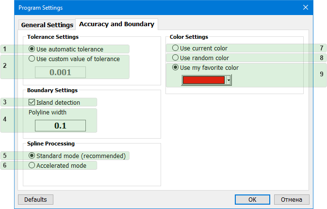
Fig. 3
The AreaTester program settings. Accuracy and Boundary tab
The AreaTester program settings. Accuracy and Boundary tab
Tolerance Settings
- (1) Use automatic tolerance • Allows the app to automatically calculate the optimal tolerance value for a current set of selected objects.
- (2) Use custom value of tolerance • Allows the user to set the required tolerance value. Excessively large or small values must be avoided when manually setting the tolerance value. This can in some cases lead to a significant delay in the operation of the app due to redundant mathematical calculations.
Boundary Settings
- (3) Island detection • Allows the program to detect enclosed areas (islands) the outer boundaries of which are entirely located inside a boundary of a larger size.
- (4) Polyline width • Edit box for setting the width of the polylines.
Spline Processing
- (5) Standard mode • At the stage of detecting areas, the program, using the method of piecewise linear approximation, converts mathematical models of splines into sets of lines and arcs entities. This option is the recommended option for most drawings.
- (6) Accelerated mode • Allows the program to perform calculations with splines as with integral objects, without using preliminary transformations. This is an additional mode of operation of the app, allowing in some cases to speed up the process, especially if the original set of objects contains plenty splines.
Color Settings
- (7) Use current color • Sets the current color of AutoCAD to objects formed in place of the detected boundaries.p
- (8) Use random color • Generates and assigns random colors to objects formed in place of the detected boundaries.
- (9) Use my favorite color • Sets a custom color.
Default settings
To restore the original preset settings, use the Defaults button (see Fig. 4):

Fig. 4
The Defaults button restores original preset settings
The Defaults button restores original preset settings
